Pages

Sunday, March 25, 2012

If all else fails, read instructions...

Last week I couldn't get the header bolted on the engine because the sub-frame was in the way, well after re-reading the instructions I "discovered" the header needs to be bolted in place before installing the engine.  I bolted the header on, and slipped the sub-frame on the engine and BAM it fit.
Now that I'm done with that fit verification, I took the sub-frame back off and bolted it up under the car.  There are 4 extra holes that needed to be located and back drilled to the car.  I was able to install the subby, then mark and drill the holes, that was a nice easy straight forward task.
That was the last of the messing around with the sub-frame so I put it in the sun and gave it a fresh coat of paint to eliminate all the scratches I put in it.  I was able to clean and paint some other little pieces, and started to take the suspension arms, and hubs apart to paint as well.
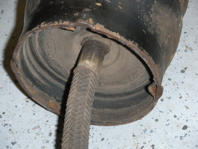
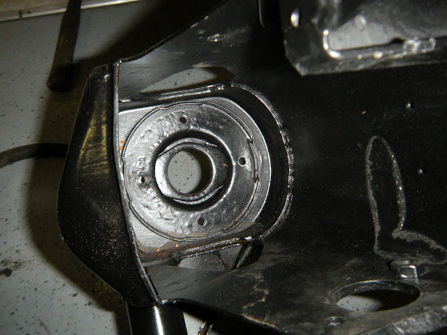
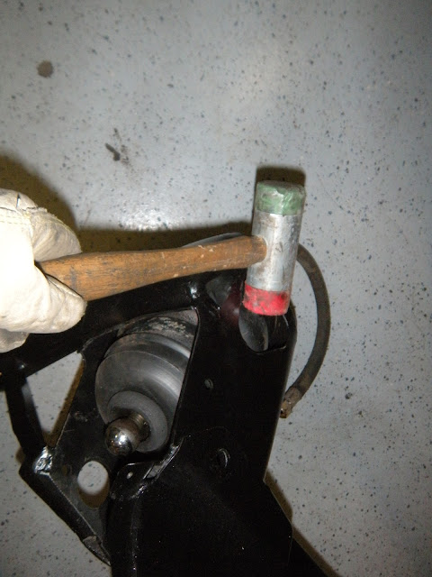
Next I was able to clean up the two hydrolastic displacers (sounds like something that belongs on the Millennium Falcon) and install them.  I had such a hard time getting them out and now that they are all clean I know why.  There are 4 little tabs that engage the mating collar inside the sub-frame tower.  You simply push the displacer up and give it a hard twist till they lock.
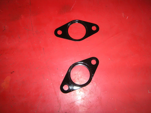
As of now, I can't install any more parts as far as the sub-frame goes because I need two $1.50 little nylon caps that have worn out.  They go into the upper suspension arms that need to be installed before the engine goes in the sub-frame.  I hope to have these in the next few days but that gives me time to paint the upper arms with POR-15 anyway.

Header and engine fit like a glove in the sub-frame.

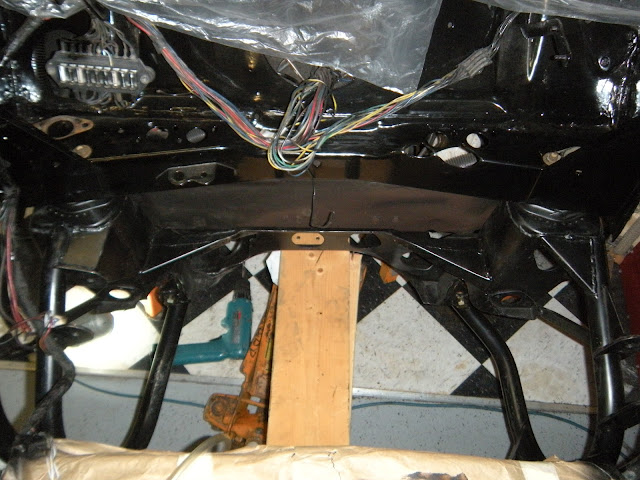
Looking down at sub-frame (supported by wood and a floor jack) is up and in the car.

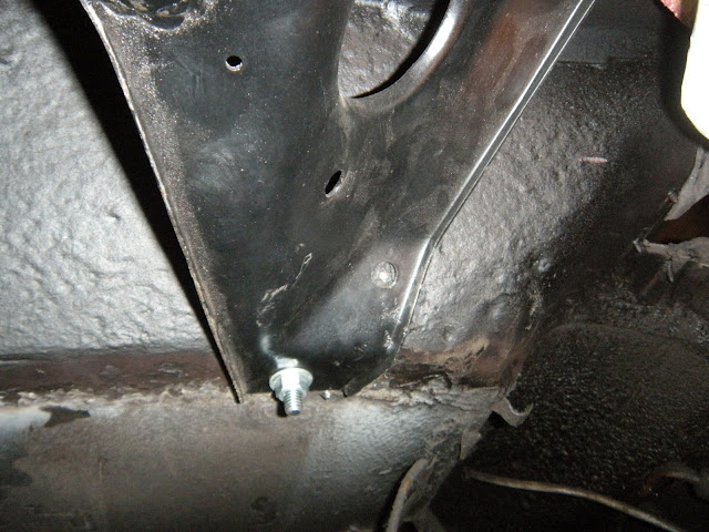
Putting in fasteners.


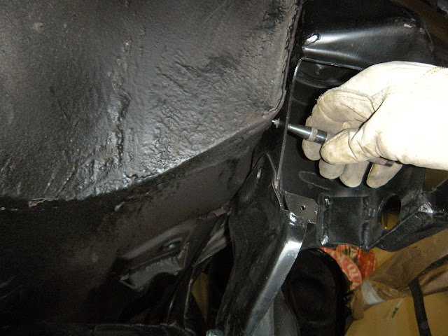
There are four extra bolts used to secure the subby, here I'm back-drilling a hole for one.

Punching a mark for another hole.

Frame is now all done being fitted, time for some new paint.


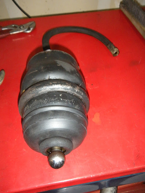
Here is a displacer all cleaned up, with a new seal and ready to go.

The four little tabs (three visible) are what lock the displacer in place.

You can sorta see the four mating slots for the displacer.  I wish I knew about those while trying to pull it out.

This is how you twist the displacer clockwise, hit it at an angle with a rubber mallet.

Displacer installed

Some other parts I cleaned up and painted.

This bolt is right in the way of a track-rod, it's hollow and has a spring in it too.  I need to cut, weld, and machine in some groves so I can install it and have it flush with the aluminum transmission case.


Monday, March 19, 2012

Engine Mounted in Sub-Frame

This week I received a new correct engine mount from Acura as well as a new MSD fuel pump.

After a good long time of using creative swear words, I finally found the correct ones and the frame dropped onto the engine with the engine mounts in place.  All it took was a grinder to remove the offending areas on the frame.  I'm not sure why I had to modify the frame, could be a slightly different engine casting, or the hydrolastic frame is a bit different than the dry frame.  Either way I was able to get the engine mounted but discovered I can't get the header to fit.  I had the header ceramic coated so I can't grind on that, I'll have to grind on the engine a bit and as for the area on the frame that hits, I'll hit it back (with a big hammer!).  I love "cold forming"...
All in all I only had a about two hours to work on the Monster Mini this week.  I'll have to push it if I wish to get this project done by summer so I have time to drive it before the weather turns to crap again.
Lastly I cut two areas on the clutch slave cylinder so after everything is in place I can remove it if I have to.  As it is, the bolts can't be removed due to the sub-frame being in the way.

Fuel pump and correct Acura engine mount.

Here the engine is mounted in the frame but the header won't go in all the way.  It's hitting at the arrow in the front...

And hitting at the arrow on the block.

Here is the engine cradled in the frame after I rolled it right-side-up.

Engine/tranny and sub-frame together at last.

Clutch slave cylinder with mounting holes cut out for possible later removal.


Monday, March 12, 2012

Frame/engine/hub fittings

This week I gave up on acid etching the engine/tranny and just sprayed it down with Purple Power degreaser and scrubbed it with a broom then pressure washed it.  Then I fit the frame to the engine after pulling the crank shaft pulley.  The only problem is the front engine mount is way off to mounting with the frame.  A new different/correct one is on order.
Also I got the new bigger "S" CV joints and flanges.  They fit in the drum break hubs perfectly.  The only problem is the length is a bit off from the the other CV joints that I had in the past.  I now need to make a wheel spacer about .37 inch to put the disk back in line with the calipers.

Frame fitted on engine (upside-down) loosely.

Clean engine with frame and header.

Hub/CV/Disk/Flange (note gap between flange and disk) old 1 inch wheel spacer is on left and will need to be machined down.

Sunday, March 4, 2012

The Quest for Clean

The test candidate.


Good degreaser, didn't touch aluminum oxide.


I had some break cleaner, why not?  Didn't work.

Typical auto parts store cleaner, aluminum is still the same.
Here is a close up of the oxidation on the alternator.

The alternator foaming with some "Aluma-nize" (phosphoric and sulfuric acid).

End result after hosing down with water, the sheet turned bright however the cast aluminum turned darker.  Uh oh...

The tranny on the left is how the alternator started out looking.  The aluminum cover on the right side of the alternator looks great but the casting has smut on it.


Oil Pan Notching


I need to make some room for a track bar on the suspension by removing the corner of the oil pan.  Simple cut and weld job.
Corner cut off.

Inside view.

Here is the sheet metal to be used.


I used the old corner piece as a template.
The sheet bent in a vice.
 
Trial fit.
Welded in and ground flush.
Painted and ready to go back on the engine.
Placed on the engine ready to be bolted.

Monday, February 27, 2012

Oil Pan Surprise and Cleaning Woes

In an attempt to clean the tranny, engine, etc. I wasted an hour Saturday by spraying the engine down with Gunk engine cleaner, I didn't expect the aluminum oxidation to come off but I did think the dirt would loosen up better than it did.  I even hit it with a pressure washer with little improvement.  Of course the parts aren't greasy but there is grime residue I would like gone, I'm after a clean look like from a new engine.  Next I'll try a new product (Lloyd's Aluminum Magic)  recommended to me buy a fellow VTEC Mini driver who is on the same forum that I am (www.vtecmnis.com).
By the way, my handle on that forum is "Mini Type R".  I maintain a build log on that site and have received lots of questions and answers by the group.  The string is: "67 Inno Build" located in the "Build and Work Logs" section.

One nice surprise came when I pulled off the oil pan and found an aftermarket baffle welded in.  And a peek in the engine from the bottom reviled four little oil jets that shoot and cool under each piston, see photo below.  Note: the crack in the casting is only on the surface (I hope).
The bolt is attaching an oil jet that cools the underside of the piston.

Here you can see the welded in extra oil baffle.

Baffle.

Monday, February 20, 2012

Intake Mods

Above is an intake as it starts out (slightly different than mine) with all the areas marked blue for what comes off.  I forgot to take a "before" picture so I stole this picture from Steve Alexander (the guy who built my sub-frame).
Here is the intake after I did a rough cut to hack off most of the big chunks.

Another rough cut view.  Note: in the background you can see the right angle grinder with the 1/8 inch thick metal cutting disk that worked great.  I also used a 4 inch grinding disk to get closer, then finally a flap style sanding disk to finish up.  As you start to see more and more aluminum dust on the workbench I'll take a moment to mention I wore a mask, and had a fan blowing across the area to constantly supply fresh air.

Here is the finished intake.  I plan to sand it with some mini sanding disks and possibly coating it with POR-15 silver gloss.  I also am considering media blasting the entire intake and shooting it with a clear gloss.   On the right side you can see a section on the intake runner that must be ground away for clearance.  I'm so glad I didn't punch through, but Steve said the wall thickness is about 1/4 inch so I guessed on how much I could remove; I just hope it's enough.  I started to use a scraper to remove the intake gasket (seen on left) however, the aluminum is so soft it started to gouge.  So I looked around and found an Exact-O knife (seen on right) with the long, snap-off blade extended out all the way and I used it to slip under the gasket.

Another view.  There is a 1/4 inch hole (not all the way through) that I will fill flush with JB Weld

Here is the intake flange that had gasket material stuck on it.  Next I used one of those 3M green abrasive disks (upper left of photo) to clean up the flange.  Notice the band-aid, next pic down shows more about that.

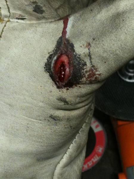
While cutting the big pieces off, I nicked the back of my thumb with the cutting disk.  Yup, right through the glove and skin and nicked the tendon.  Good times.  Cool video here.

Monday, February 13, 2012

Engine Compartment

After using the POR-15 sealer on the engine compartment, I was a bit disappointed with the look of the brush strokes.  So now I sanded the top half in order to provide a smooth base for the top coat.

Sanded firewall


Here's a shot of the glossy painted top and the rubbery undercoated bottom (there is a bit of gloss over spray on the bottom that I have cleaned up since this picture was taken).